The crackling sound produced by cell phones in an audio system is something that most of us will be familiar with. This is caused by AM demodulation in the audio circuits of the TDMA-modulated RF signals from cell phones. Especially older audio equipment, including microphones from the pre-mobile phone era can be susceptible to this interference.
If you want to check the sensitivity of your microphone or other audio equipment to cell phone interference, this RF Jammer can come in handy. However, some cautions and comments should be made here when using such an RF Jammer:
- This device will emit RF signals, which may cause interference with nearby (audio) equipment. Use at your own risk! I am not responsible for any inconveniences, damage, or any other consequence of using the device presented here, or any other RF Jammer device for that matter.
- If your equipment is not sensitive to interference from this RF Jammer, this does not mean that the equipment involved is completely immune to any radio interference. You are only testing the equipment within the frequency range of the Jammer and not in other bands. And other interference sources can be more powerful as well.
- If you want your equipment to be compatible with applicable EMC standards, it will be obvious that this device cannot be used for immunity testing against those standards. It is not calibrated and has an unknown emitted power and an unknown transfer function from its output to your Device Under Test.
With the RF Jammer as described here, I was able to generate disturbances that I felt were similar in amplitude to those of nearby cell phones. It was just a lucky shot using the generator for this purpose, but it actually works quite well. I did not try oscillator modules in other frequency bands, but I can imagine they could work as well. The AliExpress shop where I bought my RF module sells several types in the 30 to 1150 MHz range. Other stuff I bought on Aliexpress for this project includes a 20cm long SMA RG316 pigtail cable, a LORAWAN SMA antenna (male SMA version), and RK097N B10k potentiometers for the level and frequency control. (These links are just examples. I do not earn a commission when you buy from these shops.)
I drew up a schematic of the device as I made it, which is depicted here.
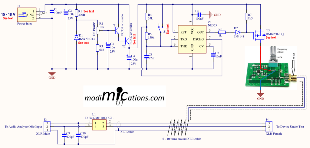
The schematic as drawn will work for 15 to 18V input voltage. The adjustable power supply circuit consisting of R1, D1, R2, R3, T1, T2, and C4 allows you to adjust the supply voltage to the RF module and control the RF power. This might come in handy if you want to search for the point where RF interference starts to kick in and becomes just audible. Then, after you have changed something in your circuit, you can find this point again. If it comes at a higher power level, you’re on the right track. But if you check the AM demodulated level in e.g. REW, you can just set it to max. Or leave it out altogether.
IC1 is a classic NE555 oscillator that generates a 217 Hz square wave. This squarewave drives a P-MOSFET, which powers the RF module with a 217 Hz signal. In this way, you create an RF generator with 100% AM modulation, mimicking the DTMF modulation of a cell phone RF signal. You can screw an antenna into the generator’s RF output and keep this antenna close to your interference victim’s XLR cable. Or you connect the RG316 cable and inject the interference into the XLR cable through the RF injector windings, as depicted further down in this chapter.
Several part types depicted in the schematic are not critical, and you can use other, similar parts if you like. E.g. D1 can be any other 13 V, 400 mW to 1 W model, T1 can be almost any NPN BJT and T2 can be any NPN BJT that can dissipate > 600 mW or so. And for P-MOSFET T3, many other similar types can be used that have an Rds,on of, say, less than 600 mOhm and Vds in the -20 V to -40 V range. I just picked the one that came up as the cheapest when I searched Mouser for such a MOSFET. Btw, this is a SOT-23 part, which is still quite easy to solder on a through-hole breadboard PCB. Alternatively, you can use a SOT-23 adapter PCB. The reason for selecting an SMD part for T3 is just because the selection of through-hole P-MOSFETs in, for example, the TO-92 package is not very large. And certainly not with a low Rds,on.
If you want to use a 24V power supply, the dissipation of R1, D1 and T2 becomes a point of attention and you will have to add a resistor in series with the power input. Alternatively, increase R1 to 2k2 and at the same time replace T2 by e.g. a BD139 BJT or similar with a heatsink. The RF generator module draws ~75mA from the supply and may necessitate a small heatsink on the BD139 at 24V input voltage. Or you just keep it stupid simple: forego adjustable RF power and use a fixed 12V power supply. R1, D1, R2, R3, T1, T2 and C4 can be omitted in this case.
I added switch S1 to switch between continuous RF and 217 Hz AM modulated RF. The only reason I also wanted a continuous RF signal was to be able to measure the frequency of the oscillator signal with a counter, so that I could make a frequency dial next to the tuning pot. If you don’t need that, you might as well omit S1.
The 217 Hz oscillator and the power supply circuit were mounted on a breadboard PCB as pictured below. On the left, you see a Male XLR that feeds the microphone signal to the Analyzer’s Mic Preamp. On the right is the Female XLR which connects to the microphone under test. Between these two XLRs is a piece of 4.5mm thick XLR cable with the injector winding. In this case 6 turns, but you can experiment with more or fewer turns to find the optimal result. On the backside of the left XLR is a Common Mode filter to reduce AM demodulation in the preamp circuit.
And now some pictures of the actual device. And when you scroll further down, there are some measurement plots.

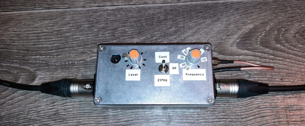
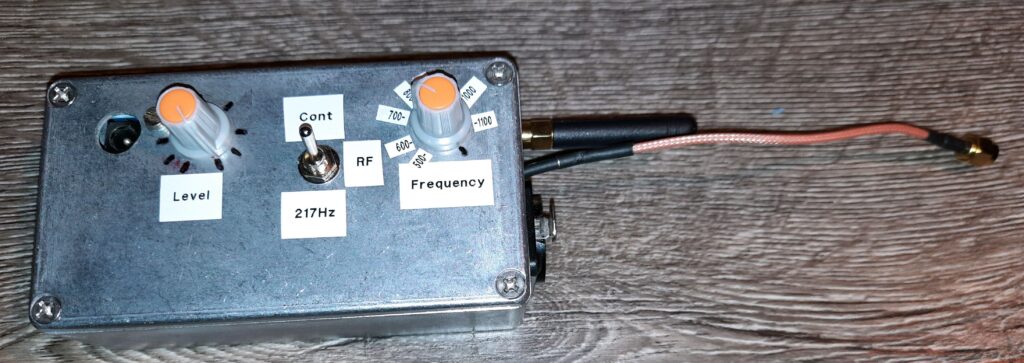
In the last photo, you see an antenna connected, which you can hold close to the XLR cable to inject interference.
The first two plots demonstrate the sensitivity of the Audio Analyzer Mic Preamp to the RF signal and the interference reduction provided by the built-in Common Mode filter of the RF Jammer. First, we connect the DUT side, which you would typically connect to a microphone under test, to the Audio Analyzer Microphone Input. For that, a male-to-male XLR cable should be used.
The second picture shows the interference reduction when the Mic Preamp is connected to the Analyzer side of the RF Jammer, what you would normally do when measuring the RF sensitivity of a microphone. As you can see, the common-mode choke is not an ideal RF filter, but I think the roughly 15 dB attenuation will generally let the interference disappear below the noise level of microphones. I tried to improve the noise reduction by attaching the ground plane of the filter PCB to the metal box through the XLR ground terminal, but it proved counterproductive. External clamp-on EMI filters on the microphone cable to the Analyzer did not work either. Perhaps a ferrite bead in the XLR cable shield will work, but I’ll try that later.
All plots were made with the Mic Preamp sensitivity set to 20 mV.
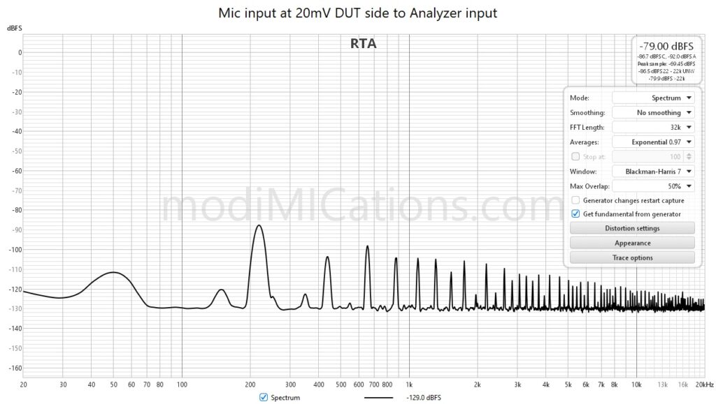
The Audio Analyzer Mic Preamp input is connected to the DUT side of the RF Jammer and gets the full brunt of RF interference from the Jammer.
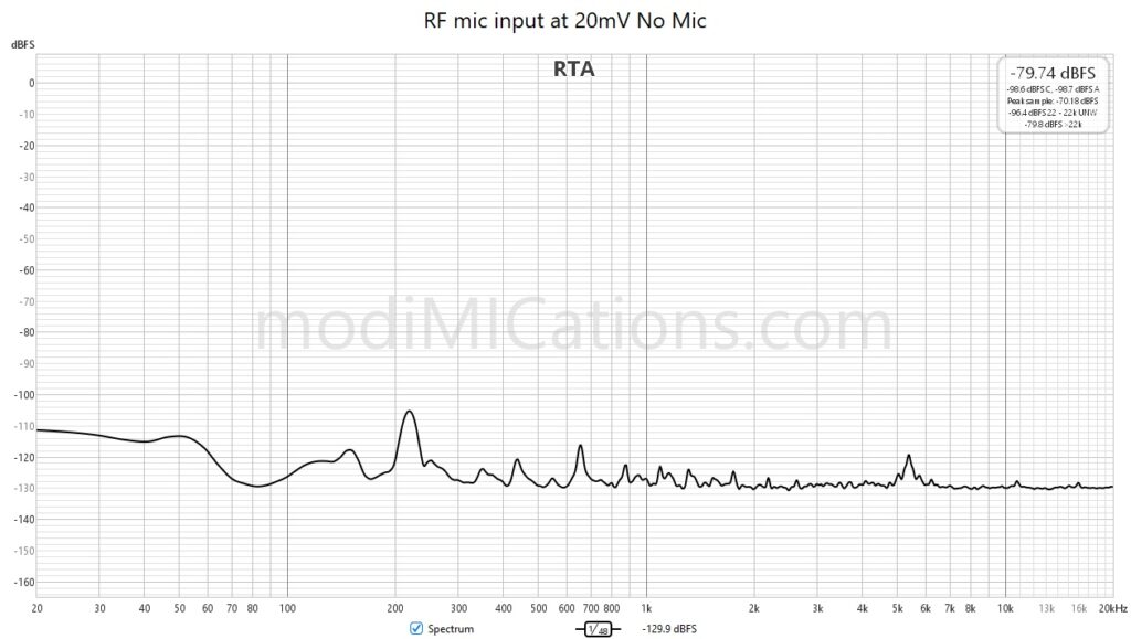
The Preamp input connected to the Audio Analyzer side of the RF Jammer. Normal use case.
As an example of how you can use the RF Jammer to check the RF sensitivity of microphones, I will present some examples of testing three different, cheap SDC microphones. The microphone under test was connected to the DUT side of the jammer through a standard, good-quality 1.5m XLR cable. The Analyzer side of the Jammer was connected to the Audio Analyzer microphone preamp input through an identical XLR cable. The injector coax cable was connected to the SMA output of the RF generator. On the Analyzer, the sensitivity was set to 20mV. RF output level on the Jammer was set to max, and the modulation was set to 217 Hz. The RF frequency was slowly swept several times from 500 MHz to 1.2 GHz and back, covering a major part of the cell phone bands. The RTA was set to Peak Hold.
The test clearly reveals the difference between a good and a bad design. First, there is the Behringer B-5, which has a more-or-less impedance-balanced, single-ended output with some caps on XLR pins 2 and 3 for RF suppression. But obviously, they do a poor job at these frequencies. It may work to some extent at lower frequencies, but not against cell phone interference. It was actually the RF sensitivity of this microphone that inspired me to build the RF Jammer, as it was this microphone with which I first experienced cell phone interference.
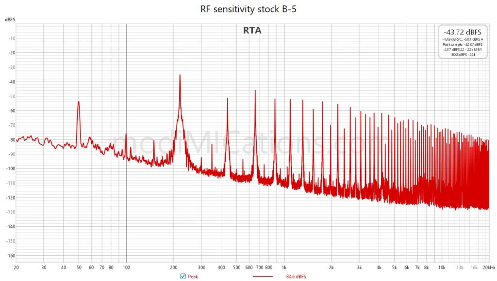
RF sensitivity of a Behringer B-5.
Things are getting much better when measuring a Takstar CM-60, which has a symmetrical Schoeps-style output. In the single-ended output of the B-5, AM demodulation will only take place in one of the outputs, resulting in a differential noise signal on the microphone output. But a symmetrical output will have two more or less the same demodulated signals on both outputs that will be presented to the microphone preamp as a common mode signal. So one can expect better suppression of AM demodulated signals, even with the same level of RF suppression (or the lack thereof).
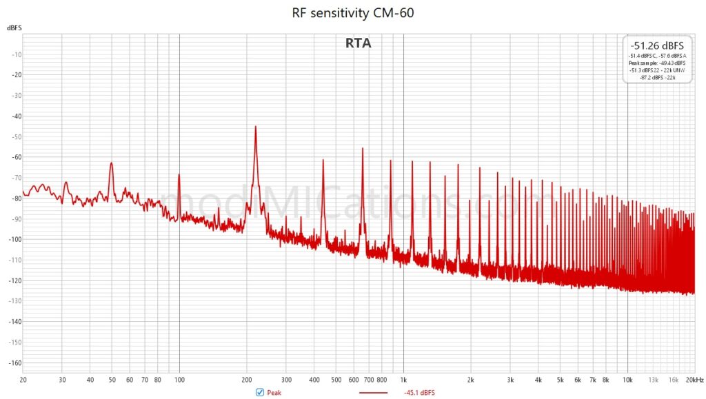
RF sensitivity of the Takstar CM-60 microphone.
Finally, with the Takstar CM-63 and the similar AKG P170, we see a perfect example of how this interference can be suppressed when the microphone has a well-designed common-mode filter in the XLR output. We see only very small peaks at 217 Hz and its harmonics that are only just peaking above the noise floor.
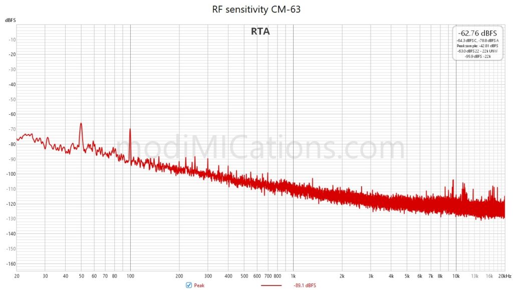
Near perfect RF suppression of the Takstar CM-63: you’ll need a magnifying glass to find the demodulation peaks.
Copyright and Terms of Use apply to this design.