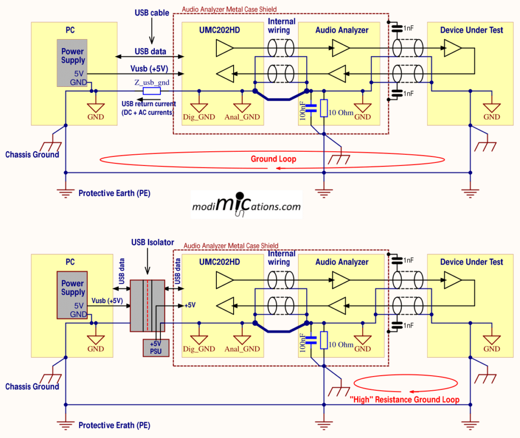
As you can see in the block diagram on the Audio Analyzer introduction page, there is a USB isolator between the PC and the Audio Interface. Before going into the details of the USB Isolator, I’d first like to explain why I have included it in the circuit. To explain what could happen if there is a galvanic connection between the PC and the Audio Interface and what would happen if a USB Isolator were used, I drew up the block diagrams depicted below. The top picture is without a USB isolator, and the bottom picture is with a USB Isolator.

Let’s start with the PC grounding. The PC has its Circuit Ground connected to the Chassis Ground (metal case), which in turn is connected to Mains Protective Earth (aka Safety Ground). The PC connects to the UMC202HD through a USB 2.0 connection, which ties the Circuit Grounds of the PC and UMC202HD, Audio Analzyer circuitry, and the DUT. All Ground and PE wires have an impedance, but for the purpose of this explanation, I have only shown the impedance of the Ground Return wire from the USB connection.
The first problem we see arising is the classic Ground loop via the PE connection, assuming the DUT has Circuit Ground connected to Chassis Ground and PE. This is not necessarily causing issues, though. If the loop area is small, which is often the case when measuring audio gear on the workbench, and if Ground wiring and cable shields are thick copper wires, the Common Mode voltages developing in the Ground connections will be small enough to not cause any issues. Ground loops aren’t a problem until they are. For this reason, next to the audio cable shields, I added thick Ground connections between modules in the Audio Analyzer as depicted by the thick wires in the block diagram. Initially, the Audio Analyzer had linear power supplies, and though the toroid transformer was placed as far away as possible from the audio circuitry, it still picked up hum. This seemed to improve when I added more Ground connections between the modules. However, completely interrupting the large ground loop through the PE connections would still be a better solution to prevent all Common Mode voltage issues.
The second issue in this circuit is caused by AC voltages induced in the USB cable Ground return wire. These are caused by the UMC202HD power supply currents, which contain a lot of 8 kHz and up current peaks, causing voltage drops across the cable impedance Z_usb_gnd. These voltages appear as Common Mode signals in the audio circuitry. These currents are also not blocked by the 10 Ohm resistor between Circuit Ground and Chassis Ground of the Audio Analyzer, because the resistor is bypassed with a capacitor to keep the two grounds connected for RF signals.
The issues described above can be completely eliminated when using a USB Isolator between the PC and the other circuits. However, there will still potentially be a high-impedance ground loop between the DUT and Audio Analyzer, but for 50/60 Hz mains hum, this should not cause any problems.
Once I decided that I wanted a USB Isolator between the PC and the Audio Interface, the question arose: which USB Isolator to choose? And what bit rate should it be able to handle? Would a Full-Speed (12 Mbps) be sufficient? Or should it be a High-Speed interface (480 Mbps)? For two-channel, 24-bit playback at 192 kHz sample rate, just over 9 Mbps would suffice, so a Full-Speed Speed Isolator would do. But if, at the same time, you have to also record at the same speed, a Full-Speed Isolator would not do. But in such cases, I could decito reduce the sample frequency. So I decided to start with a cheap Full-Speed Isolator from Aliexpress and see if that would work. It didn’t… Its 5V/5V DC-DC converter was not able to power the UMC202HD. But even when I removed the DC/DC converter from the PCBA and powered the UMC202HD through a separate power supply, it still did not work. I placed back the DC/DC converter and then tried it with a mouse and keyboard. Didn’t work either… Once again, another piece of electronics garbage from Aliexpress went straight to the electronics waste bin.
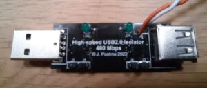
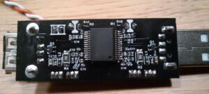
I then looked for other, High-Speed Isolators, but the few that I found were quite expensive. But TI came to the rescue: they had just introduced the ISOUSB211 chip, which would make a DIY High-Speed USB Isolator a breeze. So I decided to order the Eval kit (ISOUSB211DPEVM), which was actually quite cheap compared to the few commercially available High-Speed Isolators I was able to find at that time (mid-2022). The Eval board itself was a bit too big to fit in the Audio Analyzer, so I decided to design a PCB and build my own, which is pictured below.


The red and white wires connect to an external 5V power supply, which powers the client (secondary) side of the Isolator circuit and the UMC202HD. Do NOT use this power supply for any other of the audio circuits of the Audio Analyzer! Otherwise, you will create a ground loop and get a lot of 8 kHz and other digital noise in your signals. And that was exactly what we wanted to avoid, wasn’t it? Mind you, the USB Isolator cannot be used without an external power supply. This was a deliberate choice: a small on-board DC/DC converter may not be able to power a power-hungry Audio Interface. And secondly, such DC/DC converters may have an unacceptably high ripple voltage for audio applications.
I’m going to make the PCB and BOM available through the PCBWay store in due time. For about 20 to 25 Euros/Dollars, you should be able to build one. Mind you: the smallest parts on the PCBA are size 0402 (1005 metric). The pin pitch of the IC is 0.65mm. You’ll need good soldering skills, a soldering iron with a fine tip (0.3mm), and good eyes (or a microscope or a 5X magnifying glass). I have also made a 3D printable design for a USB-stick-like housing. If you would like to have a ready-made PCBA, drop me a line through the Contact Page. If there is enough interest, I might have a batch made, which I think I will sell for €50 + shipping.