Because of all the functions and modules combined in the Audio Analyzer, I ended up with many different Power Supplies to power all the different circuits. These are the voltages and currents required to power the complete Analyzer:
- 12V, < 8A for the PC and Touch Screen.
- +5.15V, 300mA for the UMC202HD and USB isolator (Yes, 5.15V, not 5V).
- +15V/-15V, 100mA DC for the analog electronics. Up to a few hundred mA if you drive both outputs at maximum level into a low resistance load.
- +48V, 45mA Phantom Power
- +5V for DVM module (current unknown, but PSU can supply ample power)
- +19.5V/-19.5V, 2A for the Power Amplifiers
It’s often said that an electronic device is as good as its Power Supply, a statement that I can only endorse. With many audio enthusiasts also claiming that only the cleanest of the cleanest linear power supplies would yield acceptably low noise levels, my first idea was to build some linear supplies for the audio circuits. I must say, I was quite skeptical about all those claims because there’s plenty of professional audio gear and sensitive measurement equipment around with switching power supplies. And yet, they are free from all the noise and distortion horrors that all those (audiophile) people are warning us about. And when you watch the nosie and distortion performance of this instrument, I think it proves them wrong.
Anyway, for the analog electronics PSUs, I started out using some transformers I had lying around, which seemed suitable for the job. And I bought myself some LM3x7-based kits to quickly build some analog power supplies for just a few Euros. How wrong I was: the PCB layouts were horrible, and I ended up with too much 100Hz ground ripple. So out went the PCBAs and I got myself some new ones, which were supposed to be of high quality. They were indeed, but even though I placed the transformers at the back of the cabinet, the electronics still seemed to pick up some mains hum from the transformers. Aaaand: out went all the transformers and linear supplies… I then replaced all power supplies with Meanwell PSUs. This proved to be the solution: Gone were all the hum and ground ripple issues. Admittedly, I added an LC filter to all outputs to get rid of all the spikes and reduce the lower frequency ripple, but that’s all. So this what I ended up with to power the Audio Analyzer:
- A 12V/150W Meanwell LRS-1501-12 power brick for PC and Touch Screen. It’s overspecified, but those LRS-150-12s are damn cheap, are of good quality, and are available from many shops. The LRS-150-12 powers another PSU inside the PC, which is an Inter-Tech Mini-ITX PSU 200W module. The Mini-ITX PSU plugs directly into the ITX PC board power connector.
- The PSUs for the Power Amplifier are two surplus HP 19.5W, 45W laptop chargers. I removed them from their casing and 3D printed a new box to fit both in. I did that because the mains plugs and stiff charger cables were a nuisance when mounting the PSUs in the cabinet.
- All other 5 PSUs were Meanwell RS series, 15W. They were way overspecified for the job, but they were convenient to use and easy to assemble into the Audio Analyzer cabinet. And only ~10 Euros a piece, or so.

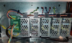
Five daisy-chained Meanwell RS series PSUs for 5V digital, 5.15V analog, +/-15V analog, and 48V Phantom power. On the left is the internal mains distribution board.
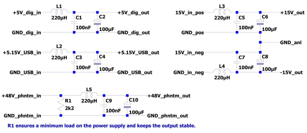
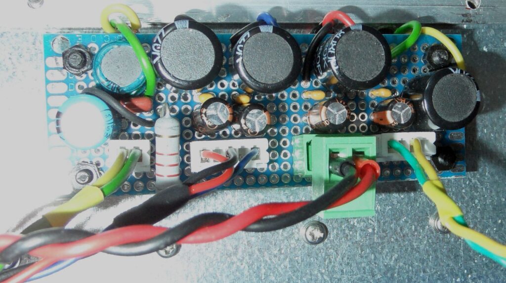
As already mentioned, these PSU needed some filtering on the outputs to get rid of the switching ripple. Each output was filtered as depicted in the schematic. All parts were mounted on a breadboard PCB as pictured below. The exact cut-off frequency is not that important, but should be chosen well below the switching frequency of the PSU. Depending on the supply filter caps on each rail, with the 220μH inductors, it will be 500…1500 Hz range. A word of caution: When using such LC filters to filter out the ripple, one must be careful not to introduce supply voltage swings due to the high-Q resonances of these filters. To avoid resonance, the resistance of the wiring plus the inductor should be such that the Q of the filter remains below 0.7. For a worst-case calculation, assume the load is a constant current load, thus having infinite resistance. Let’s do the math for the 15V supplies, which have a 220μH + 600μF LC filter. The minimum series resistance for a Q of 0.7 is now calculated as R >= 1/0.7 *sqrt(L/C) = 0.87 Ohm. I measured the total circuit resistance, which was 240 mΩ. So I expected quite some ringing on the supply rails if I connected a 100 Ohm resistor to a Line Output and would drive it at its maximum output level at a frequency of 440 Hz. Nothing of that at all… So there must have been enough other damping in the circuit keeping the Q down. I also did not observe any ringing on other rails, so in the end, I did not have to add any series resistance in any of the power rails.


Grounding:
An important part of a power distribution scheme is how to connect all the ground nets of all the modules. I didn’t trust a commonly applied (distributed) star-ground to work well, even though the inputs are measuring differentially. Ground currents could cause common mode voltages to occur in loopback tests. I also could not prevent some ground loops to be introduced in the single-ended audio connections to and from the Audio Interface. So I decided to do just the opposite: connect the grounds of all modules via as many connections as was practically possible. One would not achieve the same quality ground as a ground plane when all electronics were assembled on a single PCB, but it worked out well. Initially, I had hum being picked up from the power transformers and from the environment, but when improving the shielding of the cabinet and adding more ground connections between the boards, all hum issues disappeared. As my EMC teacher once proclaimed to his disciples: Ground loops are not an issue until they are. And in this case, they weren’t.
To avoid large low-resistance ground loops in the wiring to the Device Under Test, which might be connected to earth (safety) ground, I placed a 10 Ohm, 2 Watt resistor between signal ground and the chassis ground near one of the input XLRs. This is R1, depicted in the Line Input schematic. This is a commonly applied trick to avoid ground loops, while at the same time avoiding large common mode voltages between two connected devices.