If you want to measure the polarization voltage (aka the capsule bias voltage) and you do so with a DMM with 1M or 10M input impedance, you’ll notice that you are measuring unexpectedly low values. The reason for this is the high output impedance of the bias generator circuit. A typical bias generator can have an output impedance of over 100 kOhm, as we’ll see later. The generator output is then followed by 1 or 2 RC low-pass filter sections with resistors in the Meg-Ohm range, increasing the impedance even further. So your voltmeter will load the circuit too much and will introduce errors that can be in the order of 10 to 50%.
Things become even worse when you probe the capsule voltage; in most cases, the capsule polarization resistor is a 1 GΩ resistor, causing a 99% measurement error when your DMM has an input impedance of “only” 10 MΩ. But measuring directly on the capsule is exactly where you often want to probe to check if the capsule has a short or a leakage path, which is not an uncommon fault in LDCs. So for fault finding, you will definitely want a voltmeter that has an input impedance of, say, 1 GΩ. When probing a capsule that has a 1 GΩ polarization resistor, you should be measuring approximately half the voltage from the bias generator output. Perhaps for such fault fault-finding purposes, you would even want a 10 GΩ input impedance voltmeter because shorts or leakage paths in the capsule may only be present at higher polarization voltages. For instance, if the polarization voltage on the capsule is halved due to the 1GΩ load of the voltmeter and thereby removes a diaphragm collapse, you may incorrectly conclude that your capsule is still OK.
Making a 1 or 10 GΩ voltmeter isn’t too difficult. There are now several ways of doing that. See for instance here and here for some practical solutions for making 1 GΩ oscilloscope or DMM probes. But you could also make a dedicated high-Z voltmeter as depicted below using a 200 mV DC Digital Voltmeter Module. Admittedly, if I didn’t have a spare 200 mV DVM module lying around, I might have chosen one of the suggested solutions from the links I shared above. Unfortunately, the DVM module had a low input resistance, 200k if I remember well, so it required a CMOS input buffer stage.
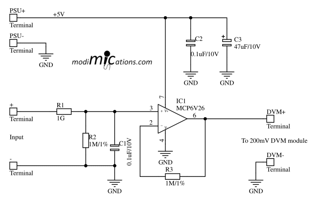
Basically, the buffer stage is just a simple voltage follower using an MCP6V26 Auto-Zeroed CMOS rail-to-rail Op-Amp with very low Vos, Ios and IB. Ideally suited for this purpose. R1 and R2 constitute a 1000:1 voltage divider. Strictly speaking 999:1, but the error is marginal and the is easily compensated for through the trimpot on the 200 mV voltage meter module. I used this one from Aliexpress (Type 1, DC 0-200 mV, or search for YB5145B on Aliexpress). If you use a 20 mV module instead, you can simply build a 10 GΩ voltmeter. Those 10 GΩ resistors are pretty expensive, though. The cheapest solution is to series connect 10 of these 5% or these 1% 1 GΩ resistors. Alternatively, you can use two of these 5 GΩ resistors. In the case of the circuit below, I consider adding another terminal for a 10 GΩ input and wiring 9 x 1 GΩ from this terminal to the 1 GΩ input impedance terminal. When using this 10 GΩ input, you’ll have to multiply the DVM reading by 10, of course.
To eliminate offset voltages brought on by the Op-Amp’s input bias current, resistor R3 has been added.
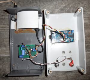
The circuit was assembled on a piece of breadboard PCB, which I cleaned with flux remover after assembly to avoid leakage paths. A 5 V power supply, the circuit depicted above, and the 200 mV DVM module were assembled in a project box, saved from an obsolete DIY frequency counter. See the picture below.
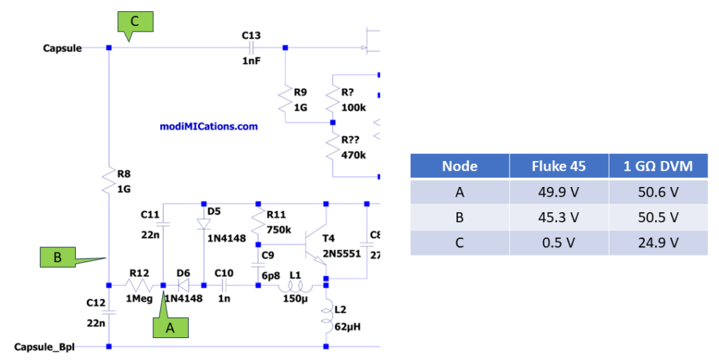
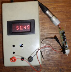
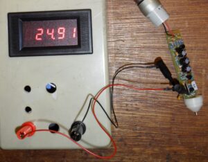
For demonstration purposes, I did some measurements on an MXL991 bias generator with a Fluke 45 DMM having a 1Ω input and this DIY meter with a 1 GΩ input. I probed three nodes (see picture below): A = generator output, B = after the RC filter, and C, on the capsule node. The results are listed below. The two pictures further down show the DVM connected to the MXL 991 PCBA, probing on nodes B and C respectively. A little math taught me that the output impedance of the bias generator was ~142 kΩ and its no-load output voltage equals 50.607 V, which is very close to the 50.6 V measured by the 1 GΩ DVM.
Copyright and Terms of Use apply to this design.