Just like with the Mic Preamp description, we start with the requirements.
- The input selector, or stepped attenuator, has the following input/sensitivity settings: Mic Preamp, 200 mV, 2 V, 20 V and 200V. Including the Mic preamp input, this should cover the whole range of small signal microphones to power amplifiers. The indicated levels correspond to -3 dBFs.
- The inputs shall be differential and have a 100k differential input impedance with a low-capacitance RF filter (~100 pF). The low input capacitance will prevent significant measurement errors when measuring high-impedance circuits (>10k) at high frequencies.
- The input protection circuit must protect the circuit against at least 230V 50 Hz, even at the 200 mV position. It should add minimal noise. The protection circuit currents must be diverted to signal ground and not to the supply rails to avoid lifting the supply rail voltages.
- There will be two single-ended outputs: one connects to the UMC202HD input, and the other to the headphone amplifier. Initially, I wanted to have an oscilloscope output, but I ended up making it a headphone output.
- There will be a True RMS converter circuit that will be connected to the DVM module.
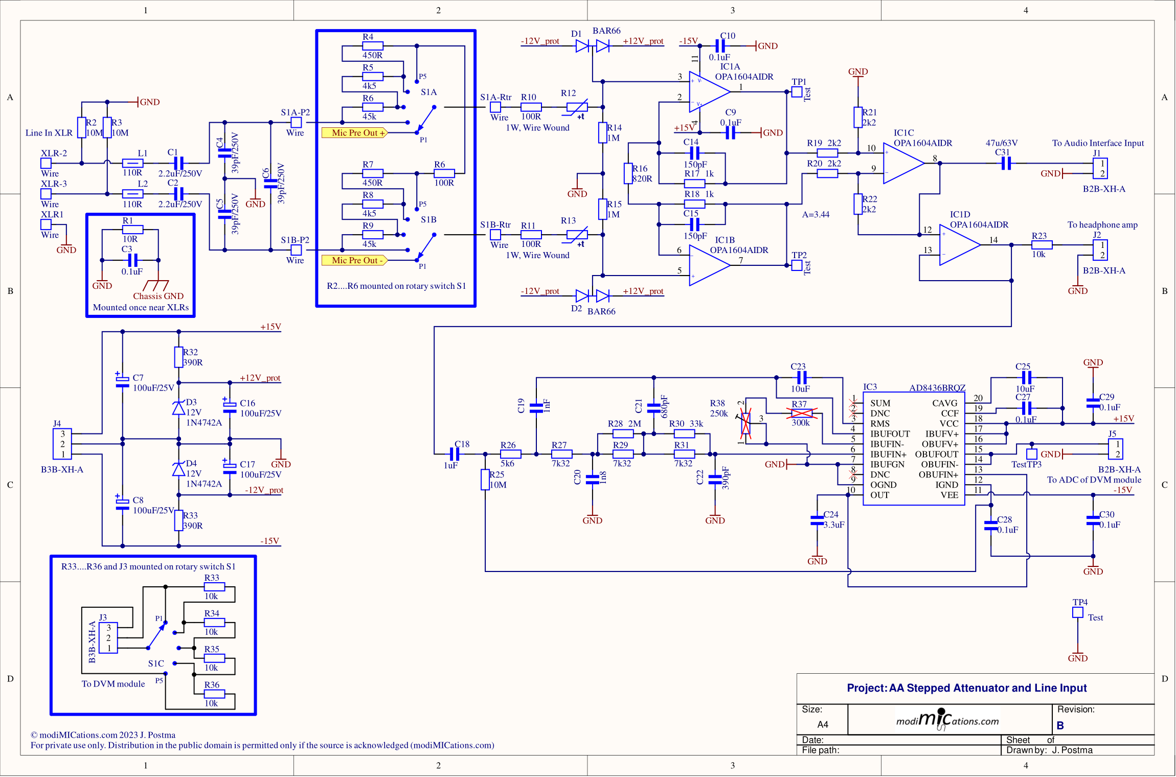
The resulting schematic is depicted below.

Stepped Attenuator and Line-Input Amplifier Circuit.
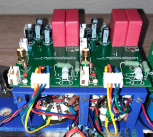
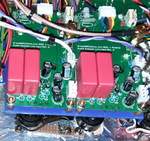
And some pictures of the two Line-Input amplifiers, the input selector / stepped attenuator rotary switches (left picture) and the XLR inputs (right picture):


Immediately obvious from the pictures are the many wires. One of the major drawbacks of how I designed the whole system. On the right picture, in the top half, you see two coaxial cables with SMA connectors. These were intended as oscilloscope outputs, but I decided later to route them to the headphone amplifier.
I will briefly go through all the circuits of the Line-Input section now.
- The parts to the left of the attenuator/selector switch comprise the RF input filter. Ideally, C6 should be at least 10 times the value of C4 and C5 for the best CMRR, but I was afraid the resulting input capacitance would be too high when measuring high-impedance circuits. I just matched C5 and C6, so the value of C6 would become less important for a good RF CMRR.
- The resistors on the stepped attenuator are 0.1% Vishay/Dale resistors. To avoid trimming, I matched the resistors for both halves of the differential input.
- IC1A, B and C comprise the Instrumentation Amplifier. For an approximate -3dBFs signal at 200 mV input, the gain of this amplifier had to be set to ~3.5. The actual gain of this circuit equals 3.44.
- IC3 is an AC to True RMS converter, to which I added an LPF to avoid out-of-band signals affecting the measurement.
- The input signal is clamped by D1, D2, D3 and D4 to approximately +/- 12.8V, so well below the Op-Amp power supply rail voltages.
- The current through these protection diodes should be limited without relying on high resistance values for R10 and R11, which would add noise if they were in the kOhm range. Sometimes, light bulbs are being used to limit the current, which, among others, AP did in their early designs (And maybe still do? I don’t know.). But light bulbs are harder and harder to get and it would require a lot of testing to find the right type. I decided to use a PTC resettable fuse for this purpose. It had to be a low-current, mains-voltage rated type. The type used here is Vishay part number PTCCL05H190HBE, which is rated for 265V and trips at 19 mA. Once it trips, it should reduce the input current to an acceptably low level. Only just prior to the PTC tripping and becoming high impedance will the protection circuit be temporarily overloaded. I made some assumptions about its robustness and simulated the overload situation. From this, I assumed it should be able to handle 230V at 50 Hz, but admittedly, I did not actually put the circuit to the test by applying mains to the input of the finished Audio Analyzer. Suppose I did make a design flaw, and I would blow up all my hard work…
Suggestions for changes and improvements
- As already said before, signal routing should be handled by small signal relays and not be routed through crappy Aliexpres rotary switches. More on this on the Microphone Preamp page.
- R10 and R11 can be increased without adding significant amounts of noise. E.g. 470 Ohm would still be fine.
- Some people might think it would help to use lower-noise Op-Amps, such as the OPA1612 used in the Mic Preamp. But it will not have a measurable effect.
- Perhaps you want to add some trim caps to the attenuator to get a better HF response on the higher attenuation settings. I did not check the HF response yet at 2 V and higher settings. Maybe they are not even needed in the audio range.