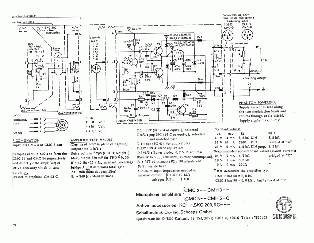
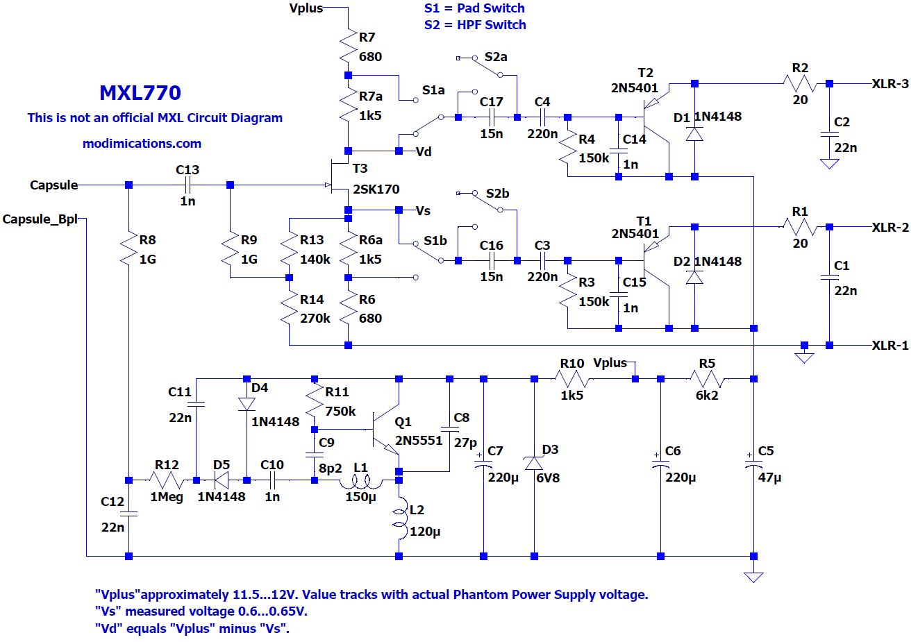
As most of you will know, you cannot connect a condenser microphone capsule directly to the microphone input of a mixer. You’ll need an impedance buffer with an extremely high input impedance (Zi > 100 MΩ, often 1 GΩ), a JFET or tube input stage, and some more electronics to match it to the kΩ range input impedance of a microphone preamp. Traditionally, tubes and transformer circuits were used as buffers, but due to the many disadvantages of both tubes and transformers, low-voltage, low-power phantom-powered JFET buffers have become more commonplace. The most popular implementation of such a circuit is known as the Schoeps circuit, named after the famous microphone manufacturer Schoeps. The circuit diagrams below show the original Schoeps circuit and one of the zillion incarnations found in popular (budget) condenser microphones. The Schoeps-style circuit depicted here is from the MXL 770 condenser mic.

Original Schoeps JFET transformerless condenser microphone buffer (public domain circuit diagram).

Schematic of a reverse-engineered MXL770.
Referring mainly to these two circuits, I will analyze the circuits and discuss some potential improvements. The order in which I’m going to cover all the topics will be more or less the same as the signal path through the circuit. The main topics I will address include:
- Capsule properties and distortions
- Capsule wiring (a.o., its parasitic properties and active shielding)
- Capsule biassing circuit (including crosstalk to the audio circuit)
- PCB (material selection, cleanliness, avoiding moisture sensitivity)
- Input capacitor (and more generally, any capacitor in the audio signal path and power supplies)
- JFET Gate bead
- JFET input capacitance-induced distortion and attenuation
- JFET biassing, JFET selection
- Coupling capacitors
- Bandwidth-limiting capacitors
- Output stage buffer design (distortion, CMRR, component matching, single-ended design or balanced)
- Output-stage protection diodes
- Output filters (bandwidth limiting, RFI filers)
The analysis will be supported by simulations done in LTSpice and by measurements on the MXL770 PCBA that I own, or on dedicated test circuits.
“Alice” variation by Scott Helmke http://www.scotthelmke.com/alice-mic.html
Scott Dorsey mod https://www.recordingmag.com/resources/recording-info/mics-miking/making-mics-better/
<<< To be continued >>>