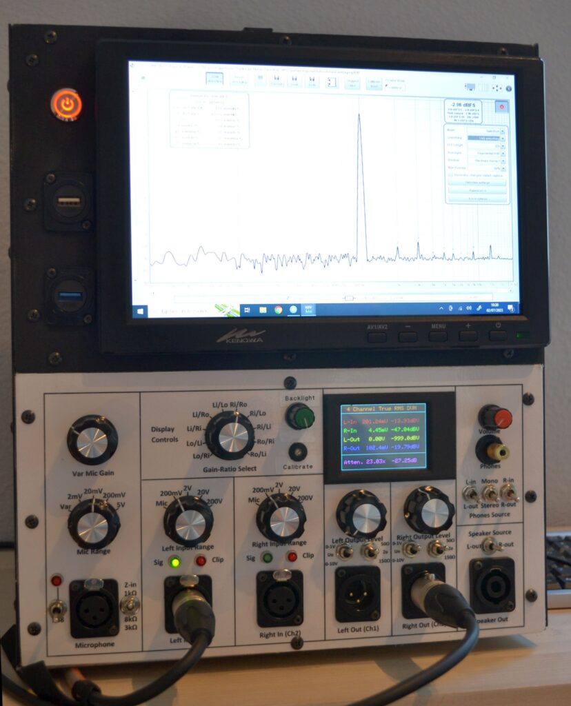
Many DIY audio hobbyists dream of having an Audio Precision or Rohde & Schwarz audio analyzer. But for most of them, including me, even a used one is out of reach. As I needed one to test my DIY microphones and speakers, I decided to build one myself around a modified Behringer UMC202HD Audio Interface, a fanless Home Theatre PC, and some self-made front-end electronics. The software will be REW, maybe Audiotester, ARTA, Virtins Multi-Instrument, or others. OK, strictly speaking, this is still just a pimped Audio Interface and the software is not controlling the added interface hardware. But I would still like to call it an Audio Analyzer because at least all the hardware is integrated into it.
Although improvements and additions can be made to the design as described here, such as adding filters, I have decided to leave it as it is right now (May 2023). That is, for the time being, I will leave it as is. Maybe I will change some circuits later if I run into limitations of the current design. Suggestions for improvements or changes have been added to the descriptions of each module.
The photo below shows the analyzer as I built it.

Why I started this project…
For speaker and microphone measurements, I used a Steinberg UR22 and Behringer UMC202HD USB Audio Interface in combination with REW and Arta software for a while. Though I like the rich feature set of the REW and Arta software, I was less happy with the system as a whole. It just takes too much time to hook up all the hardware and set up the system for a measurement with all the calibrations and stuff. This often resulted in not taking the measurements at all because of all the hassle involved. So I set out to explore the professional audio analyzer market and see what was on offer at a reasonable price. But I was soon to discover that a decent used Audio Precision or Rohde & Schwarz proved unaffordable. I was willing to spend about 500 to 750 Euros on an analyzer with the features I needed, but a used AP or R&S system would easily set me back four times as much. And they would still not meet all my requirements, as listed below in more or less random order of importance.
- The device should be a self-contained system, integrating most or all devices needed for a complete measurement setup, such as the Audio Interface, PC with LCD monitor, stereo power amplifier, and voltmeter(s).
- The integrated PC should have a 10.1” touchscreen and at least 4 externally accessible USB ports for a mouse, keyboard, USB measurement microphone, and memory stick. WiFi and BT built-in for internet access on my workbench and BT for a wireless mouse and keyboard. It should be a silent, fanless PC with an SSD drive to avoid any noise havocing the sound measurements.
- As I will mainly measure on professional audio equipment, I wanted balanced XLR inputs and outputs to easily interface with the DUT. I will make adapter cables and patch boxes to interface with Jack, RCA, or Coax connectors or for specific measurements.
- I will need just one balanced low-impedance microphone input with 48V phantom power. The noise floor, distortion and CMRR should be better or on par with a stock UMC202HD Audio Interface. Full-scale sensitivity: 2mV, 20 mV, 200mV, 5V, and variable gain. Selectable input impedances (e.g., 1k, 3k, and 8k or so). The output will be routed to the left or right input channel (selectable).
- The analyzer shall have two balanced AC-coupled high-impedance inputs (referred to as Line Inputs from here) with 200mV, 2V, 20V and 200V full-scale sensitivity. In most cases, one input would be sufficient, but e.g. for impedance measurements, you’ll want two.
- The analyzer’s Line Inputs shall be protected against overvoltages, preferably up to mains level (!). The protection circuit should add minimal noise to the measurement signal.
- Two balanced Line Outputs with max 1V and 10V RMS output level. With most measurements, one output would suffice. But I would also like to do two-tone measurements on microphones, with each tone playing through a different speaker. This prevents IMD distortion originating from the test equipment and from a single speaker, which would add to the IMD from the DUT.
- There will be two power amplifiers with Speakon outputs. Same output level as the line output it is connected to.
- There will be a Two-channel Headphone Monitor Output. The left headphone shell connects to the left analyzer input or output, and the right shell connects to the right input or output. Mono or Two-Channel (Stereo) mode can be selected.
- Input and output levels can be monitored continuously through a 4-channel True RMS DVM. Currently, I do not need to be able to perform Average or (Quasi-)Peak level measurements. Values will be displayed in Volts and dBV (dBU values are easily obtained by subtracting 2.21 dB from the dBV value, so these are not displayed). The DVM module should also display the ratio between two selectable inputs and outputs to facilitate gain or attenuation measurements.
- Signal and clip LEDs from the Audio Interface will be available on the front panel (the USB Audio Interface will be integrated into the Analyzer casing.)
- To get the lowest noise and distortion, I will bypass the input and output circuits of the Behringer UMC202HD USB. I.e. the Audio Analyzer input selector signal will connect directly to the anti-aliasing filter of the ADC. The output filter of the DAC will connect to the line driver circuits of the Audio Analyzer. Several other circuit modifications and improvements have been made to the UMC202HD to reduce noise and distortion, which will be discussed in detail.
- To avoid ground loops and PC noise injection into the measurement circuitry, there shall be a USB isolation interface between the PC and UMC202HD. Full-duplex, 24 bit/192kHz data transfer would stretch or maybe even exceed the limits of some commercially available Full-speed USB Isolators (at least the one I had failed for whatever reason), so I decided to build a High-speed USB isolator based on the new TI ISOUSB211 chip. I found the few commercially available High-speed USB interfaces way too expensive. I will make the PCB available for ordering through PCBWay in due time. Or maybe I am going to sell complete PCBAs as soldering 0402 parts is not everybody’s cup of tea.
There are several DIY Audio Analyzer projects available on the web, which are actually just Sound Card Interfaces or front-ends, that would certainly meet my budgetary requirements. E.g., there is this one by Pete Millett, another one on the Valve Wizard website, and finally this one by Menno van der Veen (Scroll down to “All about the Vanderveen-Tentlabs-ARTA-2 measuring unit”. The text is in Dutch.) And then there are the Quant Asylum Audio Analyzers, which are not DIY kits but are at least much more attractively priced than the AP and R&S products. But who in his right mind puts BNC connectors on an audio tech-related product? That really beats me… Anyway, none of these products would solve the annoying cable clutter nuisance issue on the workbench. And none of them has enough inputs or outputs. Or they had unbalanced inputs, were not using state-of-the-art components, had inadequate or high-resistance (noisy!) input protection circuits, etc. So if I wanted to have an affordable Audio Analyzer that would meet my requirements, I would have to design and build one myself. So I decided to stop my quest for an Audio Analyzer that would satisfy my needs and just build my own.
The results of my efforts will be presented in the following chapters. I hope you’ll like it and that it will inspire you to build one yourself. I will not share the PCB designs I made for my analyzer because they contain some minor flaws, and I did not update the PCB designs to the Revision B schematics. But more importantly, I was not satisfied with the overall design of the device I made. My main gripe is the wiring clutter inside the device, from the (rotary) switches to the PCBAs and between the PCBAs and UMC202HD. And talking about the rotary switches: these were bulky, yet cheap types from Aliexpress, for which you’ll almost need a wrench to rotate them and which had unstable high contact resistance. If I were to do it again, I would want to have all the switches and most of the electronics on a single PCB and use high-quality, gold-plated small signal relays for signal routing instead of expensive multi-deck rotary switches. So I would not encourage you to build it exactly as I did. But more on that later, when I will discuss potential improvements. Aside from this, I’m very happy with the performance and its features. If you want to have a sneak preview of some of the performance data before diving into the circuit descriptions, take a look here.
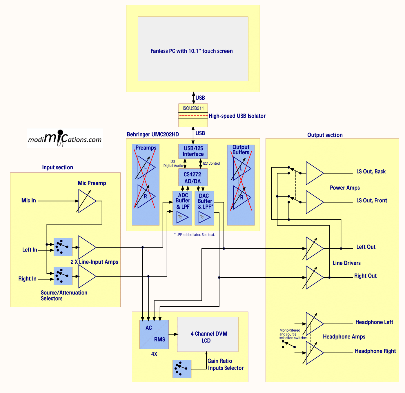
The list of requirements and wishes, as described above, resulted in the block diagram below.

Block diagram of the DIY Audio Analyzer.
In the following chapters, all the circuits, modules, and cabinet construction will be covered in detail. In the last chapter on accessories, various useful tools are discussed, such as adapter cables, attenuators, probe cables for e.g. impedance measurements, etc.
- UMC 202HD Modifications
- Microphone Preamp
- Stepped Attenuator and Line-Input
- Output Buffer
- Power Amplifier
- Headphone Monitor Output
- Digital Voltmeter Module
- Power Supplies and Grounding
- Signal Routing and Connections
- High-Speed USB Isolator
- PC and Touchscreen
- Cabinet Construction
- Performance
- Audio Analyzer Accessories