It was not my original intention to include a Headphone Monitor Output because the Audio Analyzer would readily visualise distortions long before they would exceed the threshold of audibility. So what would it add to this piece of precision measurement equipment? Yet, I hesitated because maybe it would come in handy if I wanted to do a direct A/B comparison of the audibility of certain distortions from two different sources. Or maybe I just want to use the analyzer as a media player or internet radio and listen to music through my headphones…
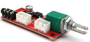
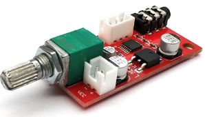
For the intended purposes, I reasoned it would not make any sense to build or buy a super-duper audiophile Headphone Amp. Just something reasonable, and especially small, as I had little space left. My eyes fell on a MAX4410 module on Aliexpress as pictured below. Just google for MAX4410 or search for this on Aliexpress and you’ll get a zillion hits for similar modules.


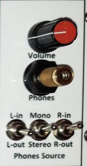
To enable A/B comparisons, I added some signal routing switches to the Headphone Amplifier inputs. These switches allow selecting Left Input, Left Output or no signal from the Analyzer to route to the Left Headphone shell and similarly to the Right Headphone shell. If you want to monitor just one channel through both shells, this can be done by setting the Mono/Stereo switch to Mono. In the Stereo position, the left and right channels are driven individually. The Headphone Amplifier controls are pictured below. In the switch positions shown, you’re listening in mono to the Right Analyzer input only. With the left channel switch in the middle position, none of the Left Input or Output signals are routed to the Headphone Amplifier.

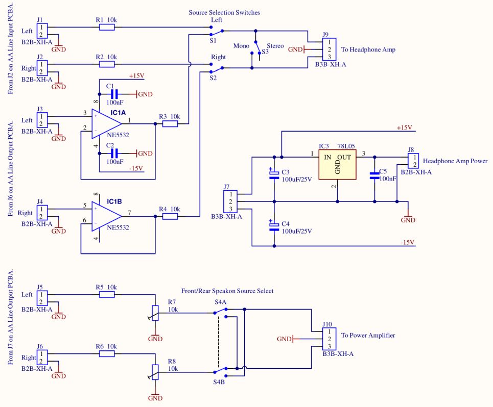
For the routing, mixing, and buffering of the input signals, I made a small circuit on a piece of perfboard. The schematic of this circuit, including the level adjustment for the Power Amplifier, is depicted below. The voltage regulator IC3 powers the Headphone Amplifier, avoiding the need for yet another power supply. In the actual circuit, I did not have the space on the perfoard for this IC, so I just took three 1N4007 diodes in series to drop a few Volts and keep the input voltage of the ASM1117 LDO on the Headphone Amplifier PCBA within the datasheet limits.
