An important factor in microphones is their frequency response, measured both on-axis (from the front) and off-axis (from an angle), because it largely determines how the microphone sounds. No microphone can reproduce the entire audio frequency range completely flat at every angle, but that is unnecessary. In fact, that is often not even desired, and it determines a microphone’s area of application. In this article, I will describe my method of measuring the microphone frequency response. It must be said that I am not entirely sure that this method is correct, and I see deviations from what others measure with the same microphones. Any comments on my method are welcome! If you like, you can message me via the contact form.
The measurement setup
Many people assume that for microphone measurements, one needs a perfect anechoic room and a speaker with a perfectly flat frequency response. But this is not true. What you do need is at least a measurement microphone with a calibration file that serves as a reference. One method of measuring the microphone frequency response was described by member MicUlli on GroupDIY here.
Unfortunately, I can’t do frequency response measurements in the living room or outside for multiple reasons. So I wanted a method that would yield usable results but in a limited space that I could do in my small workshop. So I got the idea to place the microphone to be measured in a foam booth at a distance of about 30 cm from a 5″ wideband loudspeaker. I assumed that the foam would partly absorb or transmit the sound and that only a small part would be reflected. I, therefore, expected that the radiated sound of the speaker at a distance of about 30 cm would be reasonably uniform and that, except for the low frequencies, I would also be able to measure cardioid microphones reasonably accurately above 1 kHz with an omni measuring microphone as a reference. Below 1 kHz I expected a deviating behavior due to the proximity effect, although cardioid microphones should have a reasonably flat LF response at a distance of about 30 cm. The pictures further down show the booth and all the other gear that is required for this setup.
To get good reproducible results, each microphone should be measured at exactly the same position in the booth. To achieve this, I made a 3D-printed fixture to get the microphone capsule at exactly the same location every time. For each microphone diameter, I made a replaceable disk with a semi-circular support in which the microphone capsule fits.
To allow for the height and positioning of the microphone in any position within the limited space of the booth, I purchased a 5″ SmallRig Magic Arm, which is clamped to a rod in the corner of the booth. The Magic Arm has a 1/4″ camera interface, to which I screwed a 1/4″ inner thread to 5/8″ outer-thread adapter and a universal microphone clamp. The Magic Arm has three joints, just like a human arm, and together with the joint of the mic clamp, it allows the microphone to be easily positioned in any position. Once you choose a height for the clamp on the rod, you loosen the hand screw on the Magic Arm, position and hold the mic on the alignment plate, and tighten the hand screw. With this hand screw, all joints of the Magic Arm are fixed simultaneously, making it very easy to use.
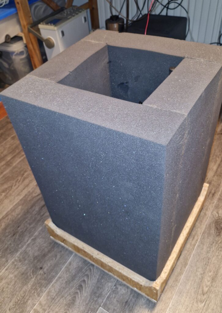
The foam booth, which is placed on the base plate. The base plate also doubles as the broadband speaker cabinet.
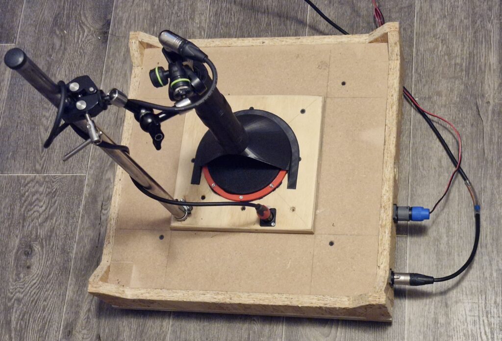
Baseplate with the broadband speaker in the middle. The removable mic alignment fixture is placed over the speaker.
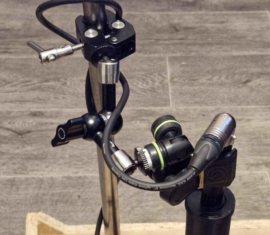
SmallRig Magic Arm with universal mic clamp, holding the Line Audio CM4 reference microphone.
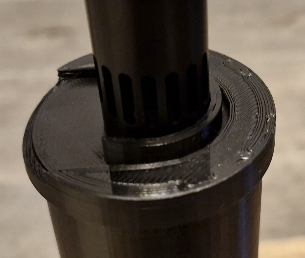
Alignment plate with exchangeable half-circle mic alignment feature. Here shown with CM4 microphone.
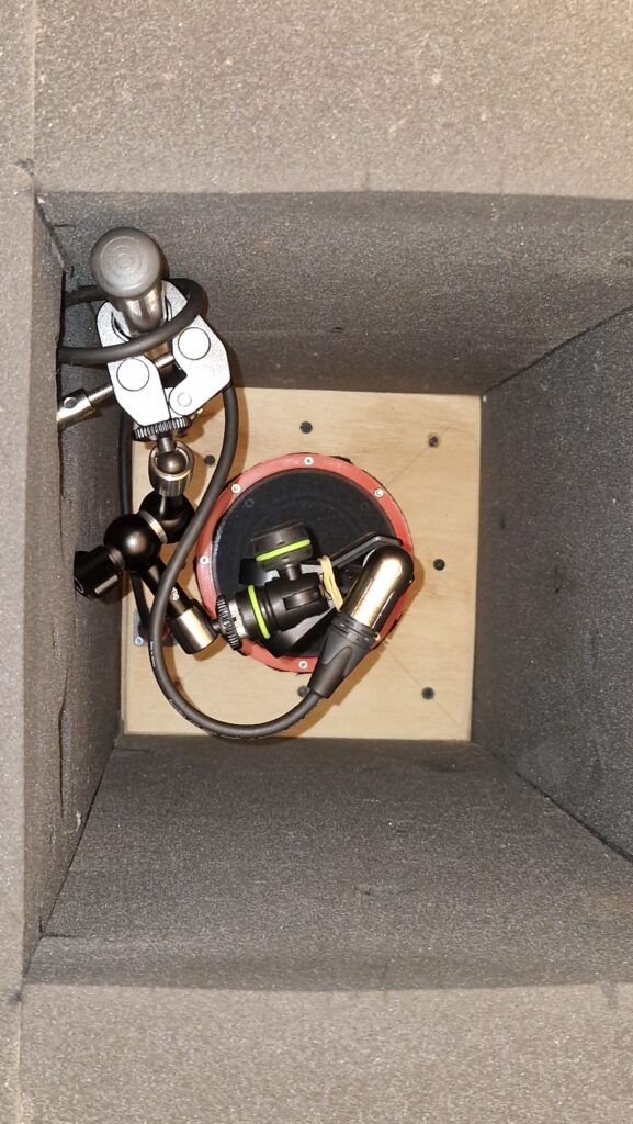
Top view of a complete setup with an aligned microphone and alignment fixture removed and the foam booth placed on the base plate.
Making measurements
For microphone measurements, you can use a PC or laptop with the Room Equation Wizzard (REW) program installed, in combination with an Audio Interface and a power amplifier. Originally, REW was meant for speaker and room acoustics measurements, but it can be used for many other audio-related measurements. I have integrated the PC, Audio Interface, a front-end with fixed amplifier/attenuator settings and an amplifier into a single measuring device, my DIY Audio Analyzer. It is very convenient to have all devices integrated, but it is not absolutely necessary to have that.
A complete microphone measurement consists of two steps. First, you have to calibrate the setup using a reference (measurement) microphone. I do that each time before every series of measurements. When you finish the calibration procedure, it yields a calibration file with frequency response data of your Audio Interface and speaker. The inverse of this response is added to the measured frequency response of the DUT microphone. A measurement of the reference mic would result in a straight line.
Calibration procedure
- Install the reference microphone as described above in the measurement setup description.
- Connect the reference microphone to a microphone input of your Audio Interface and turn on phantom power. Connect the speaker to a power amplifier of which the input connects to a Line Output of the Audio Interface. My Audio Interface has the highest crosstalk from DAC output to ADC input on the same channel, so when I choose the left side as mic input, I use the right output channel to drive the amplifier.
- Run REW and open the Preferences panel. I typically use Java Drivers and a 48 kHz sample rate. Untick the “Control output volume” and “Control input volume” options.
- Click on the “Calibrate soundcard…” button and follow the calibration procedure. When completing the procedure you will receive an error message: “Excessive variation in measurement”. Ignore this message. REW expects only a few dB deviations from a flat frequency response from a soundcard, but we use this procedure to compensate for much larger deviations from a broadband speaker that has to reproduce the entire audio band. So just close the procedure and continue.
- Click on “Make cal file”, give it a name, and store it in your calibration files folder. Close the Preferences pane.
- The calibration procedure is now complete and in subsequent measurements REW will compensate the measured values with the values from the calibration file.
Measuring a DUT
- Remove the reference microphone and install the DUT microphone in the booth. The alignment fixture helps you to position the microphone with mm precision.
- Click on the Measure button. Set “Start Freq” to 20 Hz and “End Freq” to 20 kHz, “Sample rate” to 48 kHz, and “Level” to the same value as used in the Calibration procedure, unless you know upfront that your microphone has a much higher or lower sensitivity than the reference mic.
- Click on “Check levels” and adjust the speaker level if needed. Then hit the “Start” button.
- Once the measurement sweep is complete, click on the “All SPL” tab in the measurement window. If the graph is not visible, or only partly, click on the Limits button, then hit the “Fit to data” button. You should now see a curve that is probably quite irregular and spikey and looks nothing like the smooth curves you are familiar with from the manufacturer’s specifications. Something like shown below. Don’t be alarmed… Those spikes are often measurement artifacts and not real.
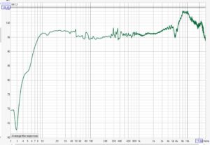
- If you want a graph that is more visually pleasing and closer to how our ears hear the frequency response, click on the “Actions” button, and from the pull-down menu, select a smoothing function. Many people use 1/3, 1/6 or 1/12 smoothing. I usually take 1/6 octave smoothing.

- When you measure multiple microphones and want to compare the graphs, they should be aligned. This is typically done with 1 kHz as the alignment centre frequency. An example is shown below, where a Takstar CM-60 (blue), Takstar CM-63 (red) and an MXL 991 (green) are compared. It won’t take much imagination to figure out what these microphones will sound like. Smoothing applied to all curves is 1/6 octave.

The same procedure can be followed for off-axis measurements. But these should not be aligned, of course, to see the rejection of the signal at various angles and frequencies.