Introduction
The Takstar CM-60 and CM-63 are two SDC microphones that are very popular among microphone DIY enthusiasts. And for good reasons:
- They are very cheap and abundantly available.
- Yet, they offer features that many other budget SDCs do not offer, such as conformally coated PCBs for good moisture protection and RFI filtering (CM-63 only).
- The 22mm diameter body tubes are very solid and capsule threads are very well machined without burrs. There’s a variety of third-party 22mm capsules available as an upgrade (a.o. from 3U Audio, Mic&Mod, and Microphone-parts).
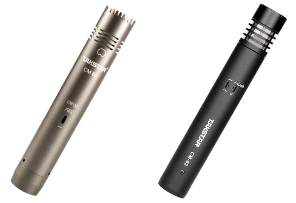
What surprised me is that they differ in so many ways: mechanically, electronically, and in finishing, even though they come from the same manufacturer. You would expect a manufacturer that offers its products so cheaply to standardize parts and modules to achieve greater economy-of-scale benefits. Even if the microphones were targeted for different purposes, one could still standardize components more than they actually did. Just look at the B9audio brochure, and you know what I mean.
Frequency Response graphs
I copied the Frequency Response graphs from the web and merged them into one picture below. In the meantime, I have recorded my own graphs, which can be found at the end of this article, including graphs from combinations of the CM-60 and CM-63 bodies with other capsules.
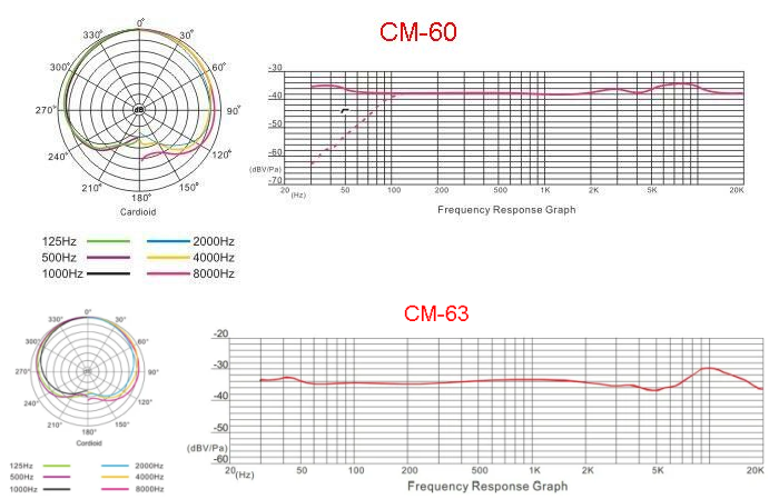
Although the graphs are not the same, both microphones have the typical high-end boost that is common with many (Chinese) microphones. And they also show the famous (or infamous) mid-range scoops before the high-end peak. Far from flat and are disliked by many if they are used for close miking instruments. The 3U capsules, and possibly also other similar aftermarket capsules, are much better. At least if you define a flatter Frequency Response as better. I have bought some 3U capsules and tested those together with my friend Boyd Timothy and we are both very pleased with the results. I would encourage you to visit his Youtube channel and listen to all the shootouts, comparisons, and blind tests that he recorded. Very educational!
Circuit Diagrams
Before diving into the modifications that can be done to the PCBAs and circuits, the Circuit Diagrams will be presented.
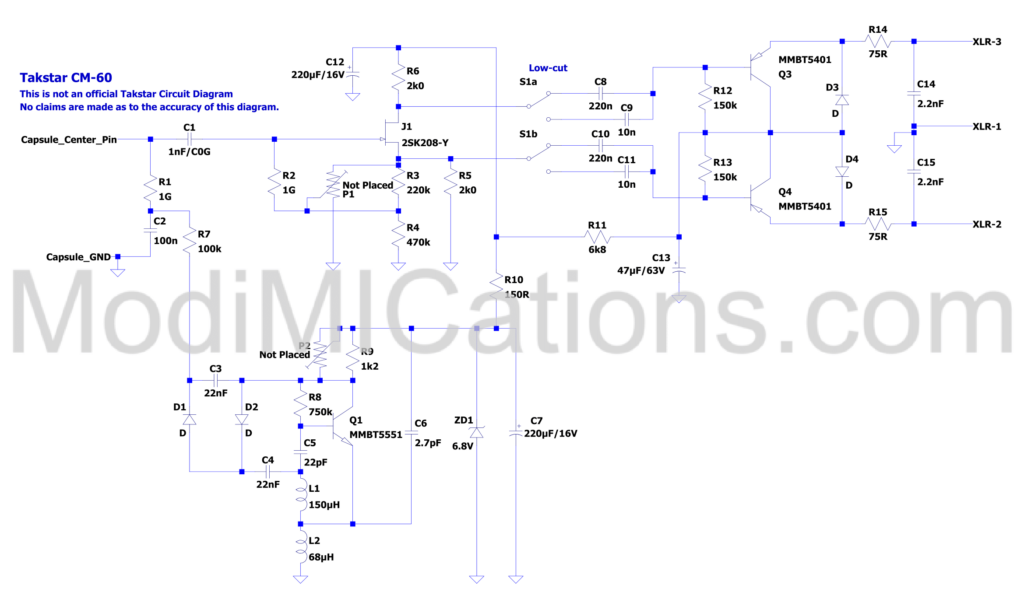
Takstar CM-60 circuit diagram. Some component values are unknown. Only those verified have been shown.
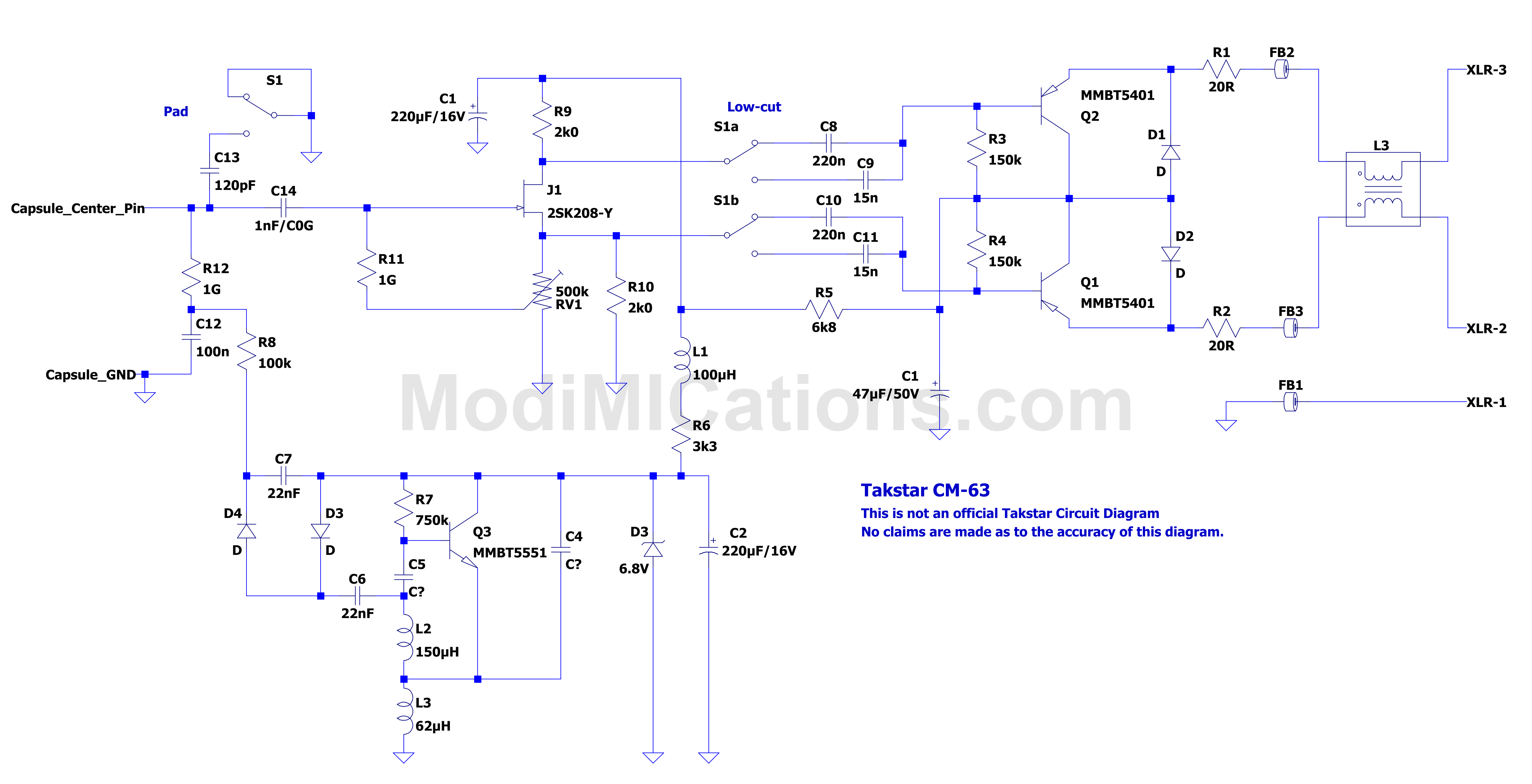
Takstar CM-63 circuit diagram. Some component values are unknown. Only those verified have been shown. GND-to-chassis connection on the XLR insert is not depicted.
Both circuits are classic Schoeps designs, with some minor tweaks and changes. For a basic understanding of the Schoeps circuit, you can read more here or here. I will confine myself here to listing a few things that stood out:
CM-60:
- There is a provision on the PCBA to place trimmer P1, which adjusts the JFET bias. But it is not placed. More on this in the modifications section.
- There is also a provision for trimmer P2, but this one is also not placed. And you’d better not do that, because it makes no sense. But the holes can be used for another mod to increase the headroom, which will also be discussed in the Modifications section.
- The RFI suppression capacitors on the outputs measured 2.2nF. In most designs, you’ll find 22nF. I think the lower values are a better choice, reducing IM distortion when using the CM-60 on high-pitched instruments at high SPLs.
- A major difference between the CM-60 and CM-63 is the supply voltage powering the JFET impedance converter/phase-splitter circuit: on the CM-60, it’s just 7.2V, while on the CM-63 it measures 13.4V. This severely limits the headroom and max SPL of the CM-60 to ~124 dB SPL. Too low to use as a snare drum mic.
CM-63:
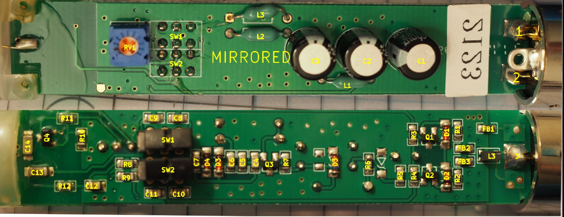
- Trimmer RV1 adjusts the JFET bias. However, Takstar’s adjustment, or lack thereof, is all over the place, as everybody who cared to measure it mentions different values. More on this in the modifications section.
- Capacitor C13 is a switchable -10 dB pad. See also the Modifications section if you want to change it to -20dB attenuation.
- Unique in this price range is a decent RFI filter in the XLR output that prevents cell phone TDMA noises. Well done!
CM-60 and CM-63 PCBAs
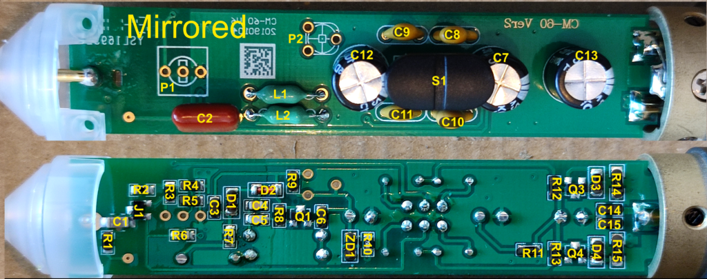
The picture above shows the CM-60 with all the reference designators projected on the parts. GroupDIY member Karl-0_0- kindly provided the picture.
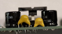
An interesting detail of the CM-60 is the slide switch. It has a rather tall actuator and if one presses on the black slide switch, it makes the actuator tilt and harder to slide. But in the picture below, you can see that the slider is supported at both ends by two electrolytic capacitors.
For CM-63 PCBA pictures, I’m posting a picture that I took from this thread on Micbuilders@groups.io, copied under the MIT License. The author, Stephanie, was so kind to project all the Reference Designators on the parts, which eases repairing or modifying the PCBAs.
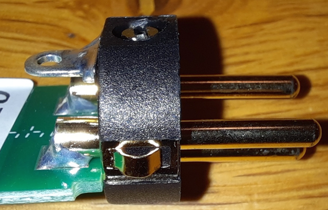
An interesting detail of the CM-63 is the XLR connector. It has a spring-loaded contact, connecting pin 1 to the chassis in the shortest possible way, which is required for effective RFI suppression. Unfortunately, these XLR inserts are hard to find, but I found them on Aliexpress here. It’s just a shame that you have to buy 100 pieces at once 😒.
Measurements and observations
Of both microphones, I measured some key characteristics and listed them together with some observations in the tables below. As said before, no Frequency Response charts yet.
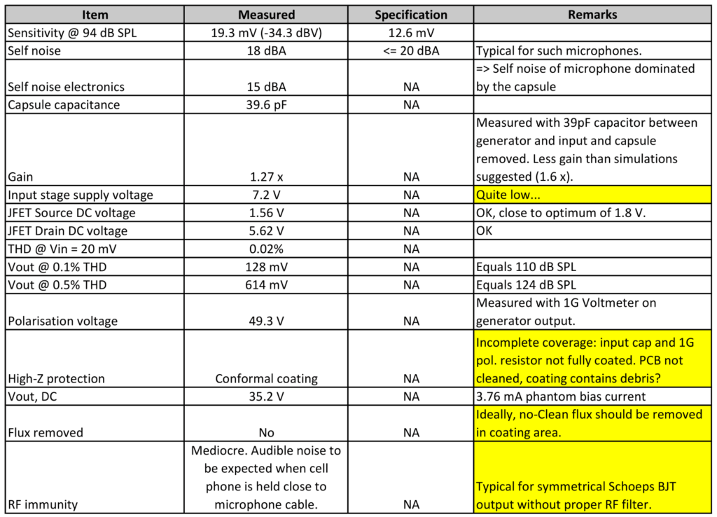
Takstar CM-60 measurement data and observations.
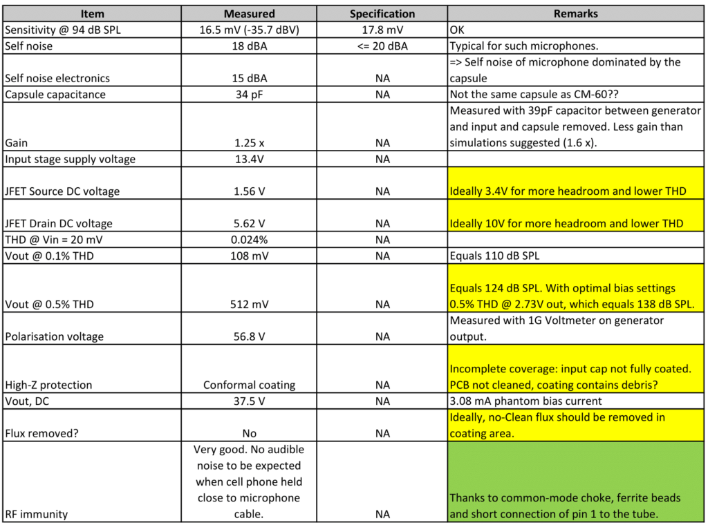
Takstar CM-63 measurement data and observations. THD measurements were done with pad switch off.
There are some good things to mention, but also some areas where Takstar could improve their products with little or no extra costs involved. This is what I notice in many products of Chinese origin: they are seldom properly engineered and are not cost- or performance-optimized.
Modifications
On GroupDIY, many modifications to the CM-60 and CM-63 have been discussed. Some are more useful IMHO than others, but that’s up to you to decide. Edit 2025-02-12: There is also an interesting thread recently started on GroupDIY regarding capsule changes. Since this is not really my expertise and I still have a lot to learn in this area, I will not discuss these changes further here. But it is definitely worth reading!
From the observations and measurement data mentioned above, we can already derive several useful improvements concerning the electronics. These include:
- On the CM-60, increase the JFET circuit supply voltage on C12 to the same level as on C12 on the CM-63. This will lower distortion and increase the dynamic range significantly.
- Although the self-noise is not terrible, it can be improved, probably by a few dB. But there are limitations, as we’ll see.
- The JFET bias must be properly trimmed for minimum distortion and improved headroom.
These modifications, and more suggestions for improvement, can also be found in this thread on GroupDIY. There is a nice summary of mods in post #30. Among others, these mods involve replacing SMT parts on the PCBA, which may not be everyone’s cup of tea. But with the right tools and after having built up some experience, you’ll notice that it is actually easier to work on SMT parts! I will dedicate a webpage to this someday.
Let’s go through all the mods one by one.
- On the CM-60, replace R8 by a 2k7 or 3k3 resistor. This should bring the voltage on C12 to the same level as on the CM-63 (~11 – 14V).
- Replace the 1G resistors with 2G or higher, if available as SMD parts. These resistors are a major contributor to the low-end noise, as you can read in my KM84 circuit description. The only drawback that I see is that you’ll have to remove the conformal coating, leaving exactly the most sensitive circuit nodes unprotected. With the coating still on and soldering through the coating, it might leave charred residues on the PCBA surface, which are conductive. I would only do this mod if you thoroughly remove charred coating debris, and clean the area with IPA. And if possible, coat the parts again, preferably with some acrylic coating. Clear nail polish seems to work well, too, but I have no experience with using that.
- Replace the JFET with a 2SK209-Y for less noise and more gain. This should work, of course, but the same notes about the coating described above also apply here.
- Now that we’ve replaced the JFET and raised the supply voltage, we can re-bias the circuit. On the CM-60, remove R3 and R4 and place a 500k trimmer. Search for Bourns 3362U-1-504RLF on the web or at Mouser. Measure the supply voltage on C12 (CM-60) or C1 (CM-63) and adjust the Source voltage to 1/4 and on the Drain to 3/4 of the supply voltage. If you have the means to do THD measurements using e.g. a soundcard and REW, you could also adjust for minimum THD or symmetrical clipping. These points are very close, but the 1/4 and 3/4 adjustments should get you sufficiently close to both.
There were several other mods discussed in the GroupDIY thread, but IMHO the ones listed above are the most important ones. E.g. it was proposed to change the input capacitor. But the one on the PCB is an excellent C0G type. When swapping it for another component, the only thing that you achieve is killing the moisture protection of the conformal coating.
The best modification you can make to the Takstars is to swap out the capsule with one of the 3U capsules or one from e.g. microphone-parts.com or micandmod.com. Note: I’ve bought some 3U cardioid capsules, and I’m very delighted with them. I bought the 1.5mm centre pin versions, though I assume the 0.5mm should also fit. I don’t have hands-on experience with the capsules from the other two suppliers. Further down this article, you will some frequency response measurements and comparisons with the CM-60 and CM-63 capsules.
A blind test where both these Takstars are being compared with several KM84 clones was recorded by my friend Boyd Timothy (aka joulupukki on GroupDIY) and shared on GroupDIY here. The blind test includes the Mic Parts SDC-84, my KM84+ circuit in a CM-60 body with 3U capsule, my KM84++ circuit in a CM-63 body and 3U capsule, a stock CM-60 and CM-3 and finally the classic KM84 circuit in a CM60 with a 3U capsule. You will also find other interesting mic shootouts in that same thread and on his Youtube channel. You should definitely check out these blind tests!
Now that we’re talking about KM84 clones: The KM84+ circuit that I developed and which was used in the the blind tests, I first designed for the CM-60. And a further development of this circuit, which I called the KM84++, I first made for the CM-63. Descriptions of both circuits can be found here.
Frequency Response graphs
I finally have a microphone frequency response measurement setup that I can more or less trust, though I do not claim a certain accuracy. In particular, I don’t know whether the low frequencies are being measured quite right, especially off-axis. Anyway, the method uses a Line Audio CM4 cardioid microphone as a reference, which is described here. I measured the following frequency responses:
- CM-60 body with stock capsule. Measured both on-axis (0 degrees) and off-axis (90 degrees).
- CM-60 body with CM-63 capsule. On-axis only.
- CM-60 body with 3U cardioid capsule. On-axis and off-axis.
- CM-63 body with stock capsule. On-axis and off-axis.
- CM-63 body with CM-60 capsule. On-axis- only.
- CM-63 body with 3U cardioid capsule.On-axis and off-axis.
1. CM-60 with stock capsule
If we look at the first chart of the CM-60, we immediately recognize the 3-4 dB bump at 8 kHz that we also see in the Takstar chart. But we don’t see the small dip at 4 kHz and the small bump at 3 kHz. But who says that all capsules measure exactly the same? At 6 kHz and above we see that the 90-degree graph no longer has the 6 dB separation between the on-axis and off-axis responses associated with cardioid capsules. So this capsule will sound differently on- and off-axis and stereo imaging will not be very precise when used in a stereo setup.
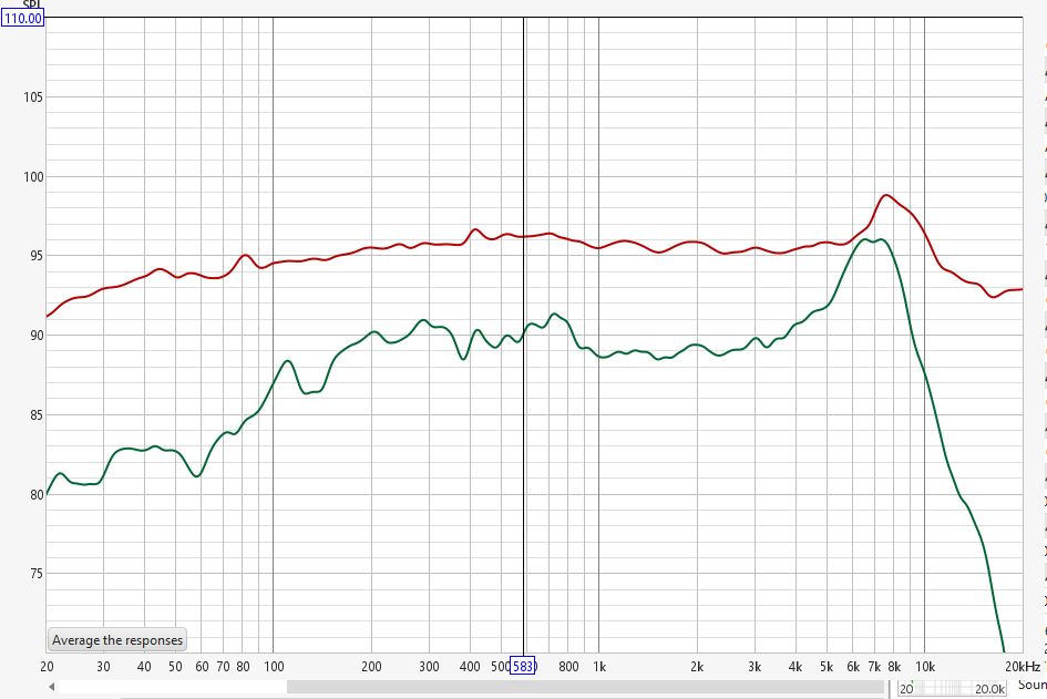
Stock Takstar CM-60 Frequency Response.
2. CM-60 with CM-63 capsule
Now, what if we swapped the CM-60 capsule with a CM-63 capsule? What responses would we get? Would they be any better? Not very likely. Indeed, the resulting graph is far from ideal, with a dip at 6 kHz and a strong peak at 9.5 kHz. Because of this, I didn’t make the effort to measure the off-axis response.
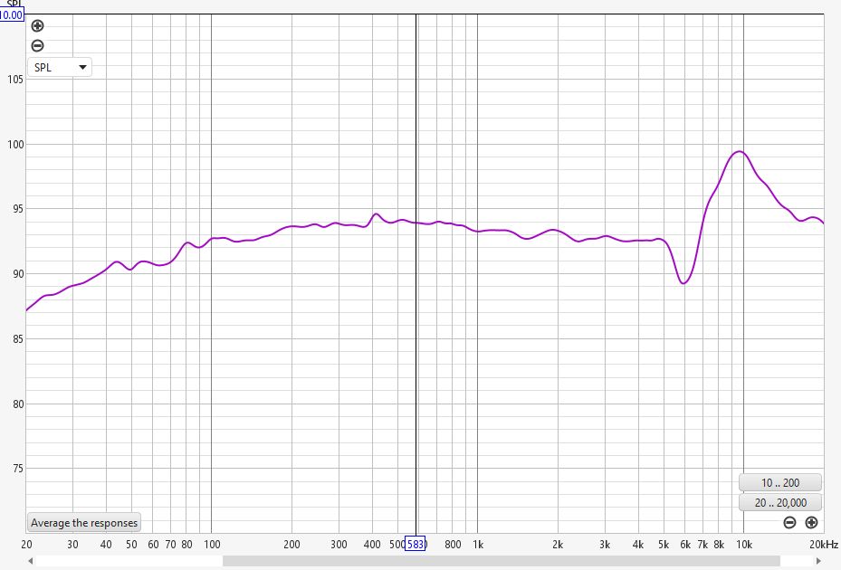
Frequency Response of a Takstar CM-60 body with CM-63 capsule.
3. CM-60 with 3U cardioid capsule
But what if we swap the stock capsule with a third-party capsule designed to work with a mic body with vents similar to those of the CM-60 body? An example of such a capsule is the 3U Audio cardioid capsule, of which I bought a pair. If the manufacturer’s Frequency Chart is to be believed, this capsule should have an on-axis response within a 2 dB range over a wide frequency span. It’s not as flat as a CM4, but it should be within the specifications of a KM84 capsule.
I assume the graph provided by 3U Audio is valid only if the body used has similar vents and back chamber design as prescribed by 3U Audio in their capsule specifications. Unfortunately, they do not specify which bodies should be usable, but we can visually compare the drawing in the specifications sheet with pictures of commercially available microphones. When you put the drawing of 3U Audio next to a picture of the CM-60 body and capsule, you will see that they are almost identical. So my guess is the CM-60 body should be usable.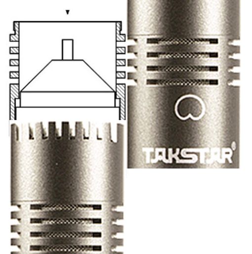
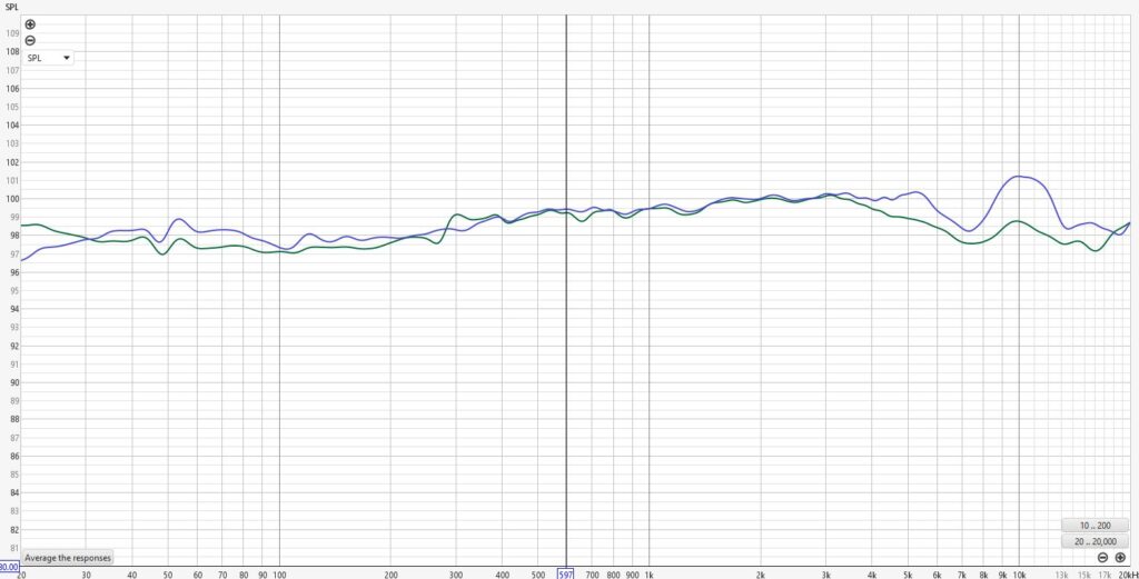
I don’t know how exactly they should match, but of the 22mm SDC bodies that I know, the design of the vents of the Alctron T-02A comes closest to the picture of 3U and its Frequency Response with the 3U capsule closely resembles the CM-60 with the same capsule mounted. The T-02A body has therefore become my favorite for this capsule, also because of the almost identical color. On the other hand, the CM-63 vents are quite different compared to the 3U Audio drawing and a different frequency response can be expected. See further down for a direct comparison between the CM-60 and CM-63 with 3U capsules.
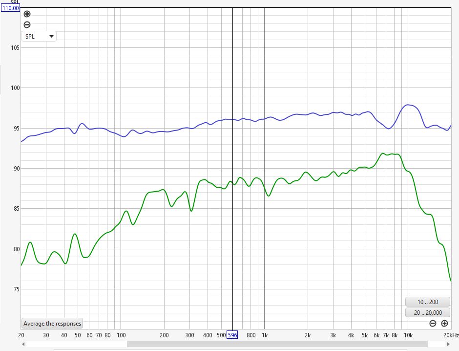
Takstar CM-60 with 3U Audio cardioid capsule.
What we see in the graph is a small bump at 10 kHz, preceded by a dip a 7 kHz. Not the same as the graph from 3U Audio, yet it’s close. But it would also be quite a coincidence that we would get exactly the same chart, even if it were measured very accurately, wouldn’t it? After all, we already know that the design of the back chamber and the vents determines the frequency response and we do not know exactly with which microphone body 3U Audio measured the capsule.
4. CM-63 with stock capsule
The next graph shows the CM-63 with the stock capsule mounted. As with the CM-60, we see here too that the graph shows similarities with that of the manufacturer. And we see the deviating on- and off-axis responses above 6 kHz.
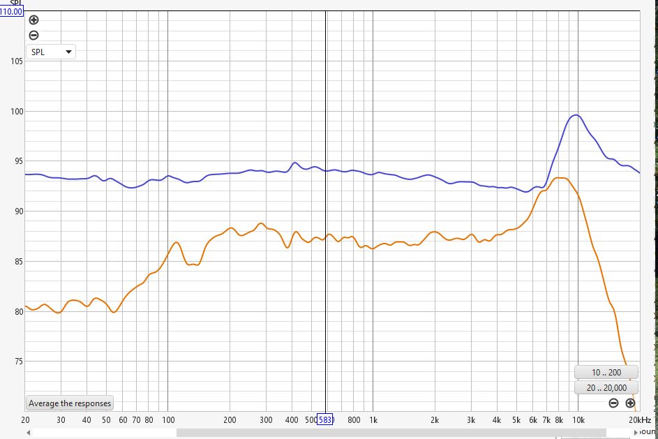
Takstar CM-63 with stock capsule.
5. CM-63 with CM-60 capsule
As with the CM-60, I also recorded the frequency response of the CM-63 using its sibling’s capsule. Nothing improved over the stock CM-63. Let’s quickly forget this option. Btw, I have no explanation for the increasing LF response.
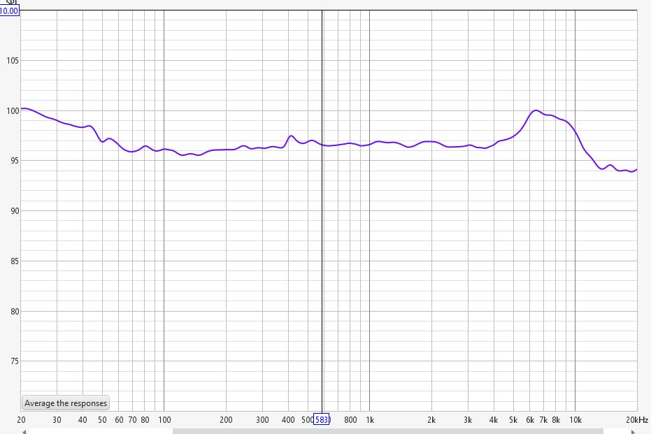
Takstar CM-63 with CM-60 capsule.
6. CM-63 with3U cardioid capsule
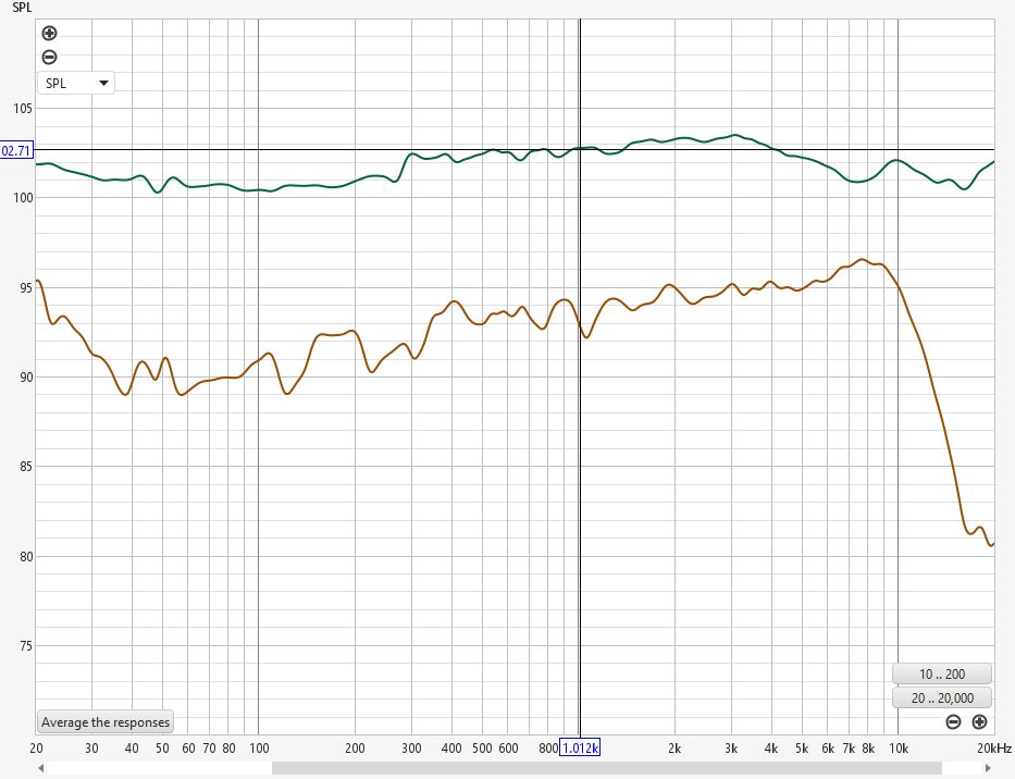
And finally, I recorded the CM-63 with the 3U Audio cardioid capsule frequency response. As already mentioned, we can expect a different frequency response compared to the CM-60 with the 3U capsule due to the different back chamber and vents design. And indeed, we see a few dBs high-end roll-off. In Boyd Timothy’s blind test, I would have expected that this would be audible and that people would prefer the CM-60 with 3U capsule over the CM-63 with the same capsule. But that was not the case. Maybe the roll-off gives a bit of a vintage sound? Or was it the sound of the KM84++ head amp circuit that made the difference? I don’t know. But I’ll also test the KM84++ in an Alctron T-02A body, so maybe that will answer this question.
The last picture shown displays the CM-60 with 3U capsule versus the CM-63 with the same capsule.
CM-63 with 3U Audio cardioid capsule
CM-60 with 3U capsule versus CM-63 with 3U capsule